The next step in building a 3D printed drone, is to lay out a more detailed plan on where to place all the hardware, like the flight controller, the sensors, the motors and the battery. This includes figuring out the center of gravity, as this is very important to keep the plane stable and designing the tail to counter balance the moment created by gravity (COG). This step can requiere a bit of iteration, since it is recommended to keep the flight controller at the or next to the COG. The same goes for certain sensors. Also, the compass/GPS module should be as far away as possible from the power lines to avoid any random disturbances due to the magnetic field. The official PX4 guide recommends to mount it on the wing.
The center of gravity
Figuring out the center of gravity was a bit of a nuisance, because of the battery. I’m using a fairly heavy battery at 238 g and if I place it behind the flight controller, the COG will be too far back, but when I place it in front of the FC, it will be too far at the front. Currently, I am planning to build a 60 cm long fuselage and the COG will be roughly at 20 cm from the front of the plane.
Connecting the servos to the receiver
The servos can be connected to the flight controller or directly to the receiver. I decided to connect them to the receiver. The main motor is also connected to the receiver. I am using the Flysky FS-iA6 6 channel receiver together with the Flysky FS-i6 AFHDS transmitter. It is old and simple hardware, but it should be enough for a first and simple project. I am going to use to servos each for the ailerons and elevators, so I will need a Y-splitter, since there is only one channel for each flight control surface. I also need an inverter for the elevator, because the servos need a reversed signal.
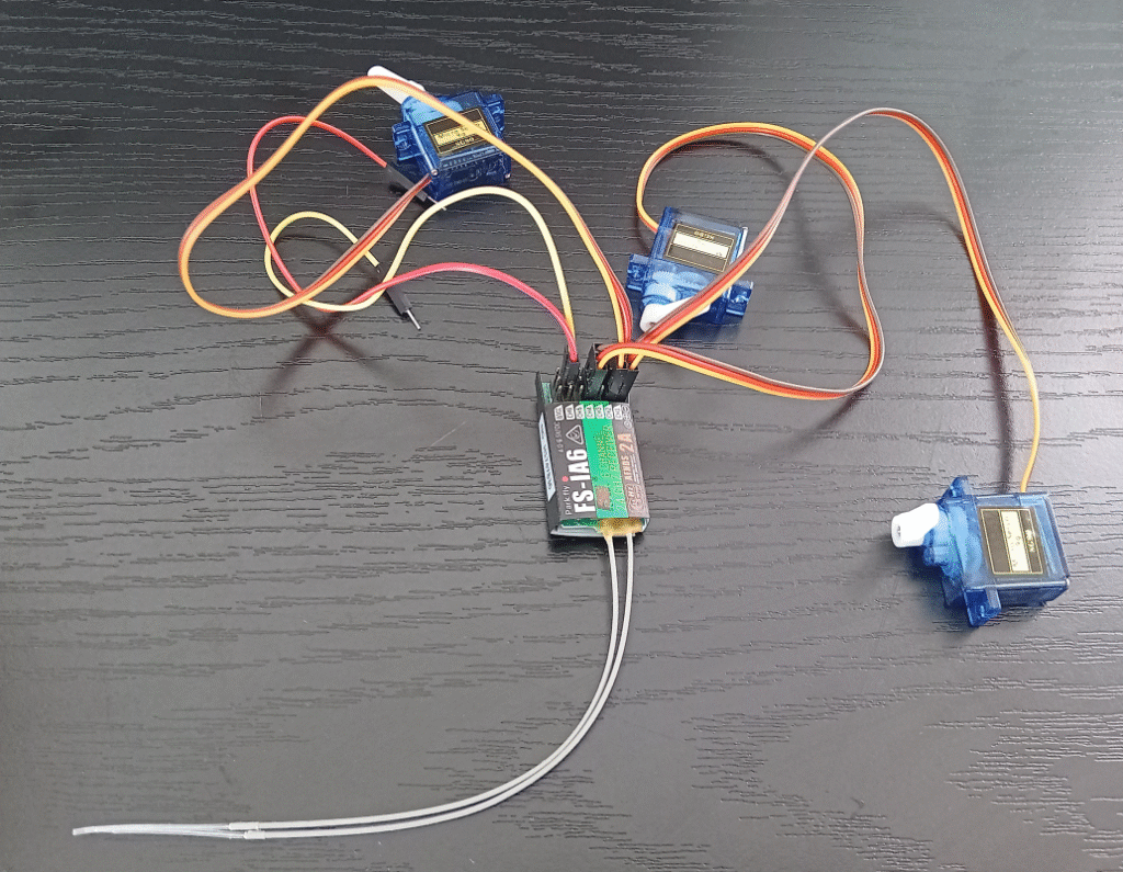
I still need to figure out, how to limit the degree of motion of the servos, so that they don’t damage the plane by rotating too much. The transmitter has an option for this, however it only seems to slow down the rotation, not limit its range.
Next, I connected the brushless motor with the ESC to the flight controller, the battery and the receiver. I soldered all the pieces together, but I did a pretty poor job (I made the mistake of soldering each pin individually instead of leaving them connected, which made them impossible to solder in the correct straight position). Luckily, it worked anyway and I managed to start the motor. It probably would have been better to cut the ESC and motor wires a bit to make it easier to place the flight controller near the center of gravity, but I decided to leave it this way for now, since I might make adjustments at some point. The next step will be to figure out how to set up and fine tune everything with Mission Planner.

Related Posts
DIY 3D printed drone project – Part 1